Patch sheets
![]() So, you own an old monophonic
So, you own an old monophonic
analogue subtractive synth and
you need to record your sound setups.
Click here for a free subtractive synth
patch sheet (pdf) which you can
download and print out.
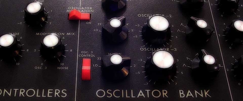
The classic subtractive synth, the Moog Minimoog.
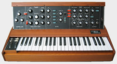
Subtractive synthesis terminology and concepts are still used in modern digital synthesis. Examples of subtractive synthesisers include: Moog Minimoog (1969), Sequential Circuits Prophet 5 (1978), Roland Juno 60 (1981).
Soundwave voltage and control voltage (cv)
In an analogue subtractive synthesiser there are two types of voltage ...
-
The electrical pressure soundwave voltage created by the Oscillators, the sound itself.
-
Control voltages which allow one part of the synthesiser to communicate with another. For example, when a key is played the keyboard sends a control voltage to the Oscillators to tell them to create an electrical soundwave.
Architecture of a simple subtractive synth
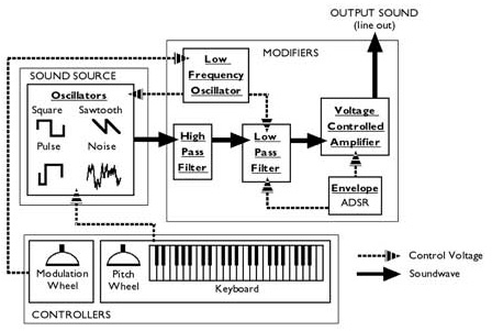
Components of a subtractive synthesiser
Each component part of a subtractive synthesiser belongs to one of 3 "categories" according to its function ...
- Controllers: These are the parts which the musicians uses to play the instrument, and include ... the keyboard, pitch and modulation wheels and foot pedals.
- Sound Source: The Oscillators, the electronic sound source where the raw electrical pressure soundwave is created. Most oscillators will offer a choice of wave shapes to chose from.
- Modifiers: Which process and modify the soundwave before it is output and heard.
Sound source (Oscillators)
An oscillator is a device for creating an electrical pressure soundwave. It is an electronic sound source. The sound source part of a synthesiser will contain one or more Oscillators. Oscillators create waveforms by adding voltages together in a manner comparable to the way harmonics in air pressure soundwaves combine to create complex natural soundwaves.
Oscillator controls on NI's Massive software synth
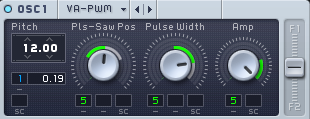
A typical subtractive synthesiser will have oscillators capable of producing different waveforms ...
Square Wave ... Good for harp and xylophone type sounds.
Sawtooth Wave ... Good for brass and string sounds.
Pulse Wave ... Good for flute and piano sounds. The exact shape of the pulse wave can be set with the Pulse Wave Modulation Control (PWM)
Noise ... Good for drum sounds and effects.
Prophet 5 LFO controls
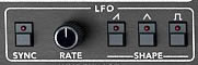
LFO (low frequency oscillator)
The LFO is an extra oscillator that does not produce sound itself, but which is typically used to create and send a control voltage to modulate (or "wobble") other settings of the synthesiser such as ...
- The pitch of the oscillators (vibrato)
- The cutoff frequency of the filter (timbre)
- The volume of the amplifier (tremolo)
The LFO oscillates at a relatively slow, or "Low", range of frequencies, usually between 1Hz and 100Hz. The LFO typically has 2 controls ...
- Speed (or Rate) which determines the frequency of oscillation
- Attack time which controls how quickly it will fade in
3 ways to control & alter sound
All of the controls on a synthesiser exist to control and alter the soundwave created by the oscillator in one of three ways ...
Controlling pitch / frequency
This can be done in 4 ways ...
- Play notes on the keyboard. Each key sends a different voltage so the oscillator knows which pitch to produce.
- Use the pitch wheel to "bend" the frequency of the CV traveling from the keyboard to the oscillators.
- Use an LFO (Low Frequency Oscillator) to send a constantly changing CV to the oscillator to make the pitch "wobble", or modulate, up and down.
- Use a pitch envelope (see later) to control pitch over time.
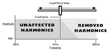
Filter cutoff control
Controlling timbre / wave-shape
This is usually accomplished with a filter. A filter is an electronic device which can selectively remove harmonics from an electrical pressure soundwave. The most important filter type on a synthesiser is the Low Pass Filter.
Full article on filter types is here.
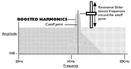
Low Pass Filter
So called because it removes higher harmonics in a soundwave whilst letting low harmonics pass through unaffected. The Low Pass Filter will be operated with a Filter Cutoff Point (or Frequency) slider which is used to determine the frequency above which harmonics will be removed and below which harmonics may pass unaffected.
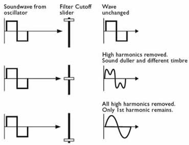
The Low Pass Filter affects the soundwave in 2 ways ...
- As harmonics are removed, the shape of the waveform changes therefore altering the timbre of the sound
- As harmonics are removed, the sound becomes duller
Filter controls on NI's Massive software synth
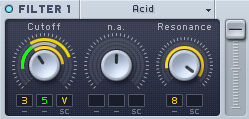
Filter resonance
The Low Pass Filter may be controlled in several ways ...
- Manually by the user setting or moving the filter cutoff point slider.
- With a CV from the LFO which will automatically move the filter cutoff point slider repeatedly up and down
- With a CV from the envelope (discussed later) which will move the filter cutoff point slider up and down over time.
- Resonance control. Accompanying the Low Pass Filter will be a slider or knob which boosts the harmonics around the Filter Cutoff Point to producing a distinctive whooshing effect.
Controlling amplitude
Once the soundwave has passed through the filter it will arrive at the amplifier where its amplitude, or volume, will be controlled before it is output. The amplifier can be controlled in several ways ...
- Manually by the user setting or moving the amplifier slider by hand.
- With a CV from the envelope which will automatically control the amplitude over time.
- With a CV from an LFO which will turn the amplitude repeatedly up and down (tremolo).
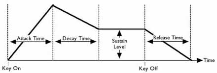
Stages of a standard 4 stage envelope generator (EG)
Envelope controls on a Roland Jupiter 8
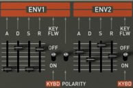
Envelope
The Envelope Generator (EG) can perform several functions including ...
- Control the amplitude of the soundwave over time by automatically turning up and down the amplifier.
- Change the Low Pass Filter's Filter Cutoff Point over time. This is useful if you want a sound to start bright and then become duller.
- Control the pitch of an oscillator over time. For example to help emulate the transients of brass instruments which don't reach correct pitch immediately they are blown, it takes a fraction of a second for the pressure to build.
- Control the speed of an LFO over time, perhaps in order to create changing modulation effects.
- etc
The most common envelope has 4 controls ...
- Attack This controls the TIME taken for the sound to build to its maximum volume on key down
- Decay This sets the TIME taken for the sound to decay to the sustain level
- Sustain This sets the LEVEL at which the sound will remain as long as a note is held
- Release This sets the TIME taken for a note to decay to silence once the key is released.
Ring modulator
Although not a commonly included module of many subtractive synthesisers, nevertheless a ring modulator is a powerful creative tool for creating dissonant sounds. It works like this ...
- 2 sound waves are input or generated (eg 300Hz and 100Hz) and copies are made (eg so there are 2 waves at 300Hz and 2 at 100Hz)
- 2 waves are summed together to create a new wave (eg 300Hz + 200Hz = 500Hz)
- The other 2 waves are subtracted leaving the difference (eg 300Hz - 200Hz = 100Hz)
- The resulting waves are played together (eg 500Hz and 100Hz)
- The resulting harmonic relationship between the waves is dissonant
So, a ring modulator breaks pleasant harmonic relationships between sounds and can be used to introduce "aggressive", unpleasant, and even "metallic" sounds into a synth patch or musical piece. These device have been much used by electronic musicians and artists exploring atonal musical forms.