Now either read on below, or watch our sister site's (projectstudiohandbook.com) video on digital synchronisation here ..
In general, individual samples in a lone digital signal will be precisely clocked during conversion, but ensuring multiple individual signals are clocked together, and overcoming problems of transmission induced jitter is more problematic.
The three essential problems are ...
- Ensuring an analogue to digital converter (ADC) in a system is precisely clocked (preferably by its own internal crystal clock)
- Ensuring the digital to analogue converter (DAC) in the system is clocked the same as the ADC (preferably clocked to the ADC)
- Ensuring that when separate signals meet (perhaps in a DAW or digital mixer), their clocks/samples are in-sync
Unlike analogue audio connections, when multiple digital audio signals meet or move together between devices (such as a digital mixer and a DAW-digital audio workstation) they must be synchronised by a common clock. Like 2 cogs in a mechanical system, they must mesh. Therefore, their sample rates will need to be identical and they will need to meet "in sync". If the signals and devices are not synchronised, audible clicks and pops will result every time a receiving device fails to correctly anticipate the arrival of samples in an incoming signal.
Here are some of the devices that may be connected together in a digital audio system ...
- DAW / digital audio interface
- A stand alone a to d converter
- Digital mixer
- Digital microphone
- CD player
- Digital multitrack
- A voice channel with a digital output
- An effects processor
NOTE: You may also wish to read Connectors in the recording studio to understand a little more about the variety and uses of digital audio connection technologies.
Where is jitter at its worst?
It is important to understand that "jitter" and "drift" only affect audio quality if they occur during analogue/digital and/or digital/analogue conversion in a ADC or DAC. If a signal had been digitised by a good ADC with an accurate clock, then any jitter introduced during processing or transmission won't be audible providing the systems DAC operates without jitter and is synchronised to the same clock source as the ADC. The DAC will eliminate any jitter generated by processing or transmission. Therefore it is preferable to choose the device with the ADC as the clock source for the whole system.
In general, given that most converters use extremely accurate crystal clock technology, audible jitter is more likely to occur during transmission down a cable than in a converter.
Master and slave
In a multiple device digital audio system, one device (preferably the ADC) must be the master (supplying a clock timing signal) and all the others will be slave devices synchronising to the master device at its sample rate. It is possible to daisy chain devices together but because of the differing digital audio connectors (SPDIF, AES, TOS-link etc) it may be more convenient to have one dedicated master clock device supplying duplicates of a single clocking signal to each slave device individually by way of independent connector leads.
Master clock devices
However, master clock devices tend to be expensive, too expensive for many project studio owners, and for complex reasons can produce more timing errors resulting in a deterioration in audio quality. This is largely because the master clock must transmit duplicate clock signals down multiple cables (and sometimes in multiple electrical formats, WC, AES etc) to all the devices in the system, and therefore jitter can be generated in the cables!
Word Clock
Word Clock is a timing reference for digital audio devices. It is a digital clocking signal running at the sample rate of the audio devices it is synchronising. The Word Clock signal is essentially a square wave at the frequency of the sample rate. Word Clock provides a measurement of the passing of time at the speed of the sample rate. It allows multiple digital audio devices to synchronise with one another.
Word clock may be embedded in a digital audio signal or generated and transmitted separately.
External stand alone master Word Clock device
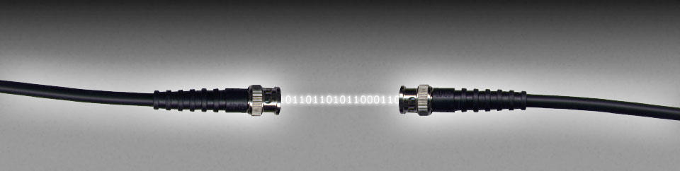
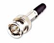
A stand alone Word Clock device (such as the one shown here) will generate multiple identical Word Clock timing signals and transmit them down individual BNC cables (connector shown) to multiple individual audio devices to ensure the synchronisation of the (separately transmitted) AES, ADAT, Toslink etc digital audio signals that pass between them.
Using a master clock is convenient but as already stated, often reduces audio quality because no matter how accurate the timing clock in the device is, receiving devices will be subject to any jitter caused by the transmission of the signal down the BNC cables. In addition, many semi-pro digital audio devices do not have separate Word Clock (BNC) input connectors.
Embedded Word Clock
For smaller project studios with devices sporting AES3, S/PDIF/Toslink or ADAT/Toslink connections, a simple and effective solution is to synchronise using the Word Clock (also called a Bit Clock) embedded in the digital audio signals themselves. One device must be nominated as the master and the rest set as slaves. It is best to nominate the device with the analogue to digital converters.
All devices will be connected together with appropriate digital audio connections (AES3, S/PDIF, Toslink etc) and will have the ability to be switched to either slave or master mode. As an example, my own system has this simple daisy chained system ...
- Voice channel /ADC (master) AES output
>>to>>
Mixer (slave) S/PDIF input - Mixer (slave) ADAT-Toslink output
>>to>>
DAW (slave) PCI ADAT-Toslink interface input
I constructed a special 110ohm resistor enabled AES3 (XLR) to S/PDIF (phono) lead to link my voice channel to my mixer (because of the voltage differences between AES and S/PDIF) and the whole system works perfectly. The only drawbacks are that my voice channel must be on or the mixer won't work, and this system only works because I have a single source (my voice channel).
If you are using embedded Word CLock and your DAW as the master, you will need the means to transmit Word Clock from the DAW to any devices that are sending digital audio signals back into the DAW. This means you will need 2 way connections to your devices, even if a device is only sending audio signals in one direction (such as a voice channel sending a signal from a microphone to the DAW in order to record it).