For example, you may need to synchronise music and sound effects to on-screen action or synchronise an analogue multitrack tape recorder and an audio sequencer (such as a Cubase or Logic system).
This article focuses on the use of SMPTE timecode.
Other synchronisation technologies
You can read about digital audio synchronisation (word clock) here.
NOTE: There are also devices known as Synchronisers which enable the transports of 2 or more multitrack tape recorders to lock together so they can function as one device. These are NOT discussed here.
What do video makers need to know?
The video maker needs to know ...
- The concepts of timecode, particularly SMPTE and embedded video timecode's such as DV
- The uses of timecode in syncing sound and picture
- The uses of timecode in automating batch capture of clips from a camcorder to a computer
- The use of timecode in Edit Decision Lists
What do music recordists need to know?
A music recordist needs to know ...
- The concepts of timecode, particularly SMPTE, MTC, MIDI Sync and Word clock
- How to synchronise a sequencer to a multitrack tape recorder
- How to synchronise two MIDI devices such as a drum machine and a sequencer
- How to synchronisation two digital device together in the digital domain, such as a digital mixer and digital effects process
A brief history of SMPTE timecode
In the 1950s US television engineers realised that the hit and miss process of post production audio dubbing (re-recording speech, and adding sound FX and music to video and film) would be much easier if it could be automated using some kind of time/clock based synchronisation system. Their union, the Society of Motion Picture & Television Engineers (SMPTE) financed the development of a new technology called SMPTE ("simpty") timecode.
What is SMPTE used for?
SMPTE timecode is now used in film, TV, video and music production and "versions" of it appear embedded in digital video formats such as DV, and the MIDI language (MTC).
Here is a list of the most common uses of SMPTE ...
- To aid the editing together of speech, sound effects and moving images during TV, film and video post production and editing
- To allow different sound recording technologies to be synchronised together during music production, such as ... tape recorders, computer sequencers, drum machine
- To aid composition and editing together of music and film, TV and video pictures
- To help automate the transfer of digital video clips between camcorders and computer editing systems
- To enable offline and online video editing work processes
What is SMPTE timecode?
The SMPTE timecode is an hybrid computer/audio signal (more on this later) which can be recorded onto ...
- a separate audio track of a portable (film location) audio recorder
- a separate audio track on film in a camera
- a separate audio track on a digital video cassette tape in a video camera
- a separate audio track (usually the highest) of a multitrack tape recorder
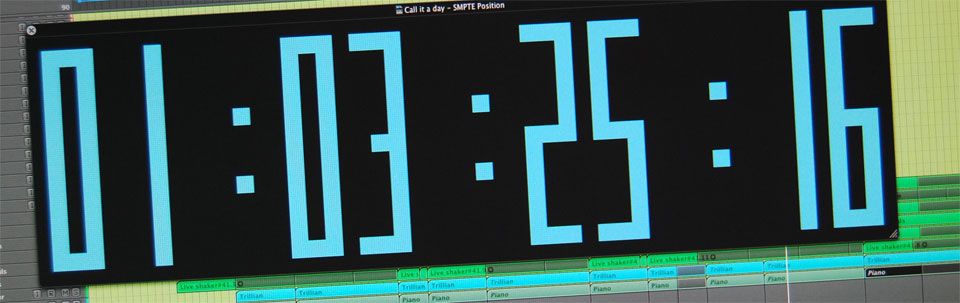
The SMPTE timecode signal carries Clock information in the form of hours, minutes, seconds and frames. Here is an example of a SMPTE display showing timing information ...
What are frame rates?
SMPTE timecode allows each individual picture (or frame) of film or video to have its own unique identifying number. There are 4 SMPTE frame rates for the four worldwide TV broadcast and film frame rate standards each identified by its unique fps (frames per second) rate ...
- 30 fps The original black and white US TV rate. Unused since the advent of colour TV.
- 29.97 fps NTSC colour television and video. Also known as drop frame. Click here for a list of countries which use NTSC.
- 24 fps Worldwide film frame rate.
- 25 fps PAL colour television and video. Also known as EBU (European Broadcast Union), this rate was created for TV engineers working with the European PAL TV standard. Click here for a list of countries which use PAL.
What is a SMPTE device?
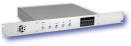
The SMPTE timecode signal is generated (and read back) by a SMPTE timecode generating device. Examples of SMPTE timecode devices include ...
Stand alone devices Film production uses these to feed an identical SMPTE timecode signal simultaneously to both cameras and audio recorders on location
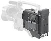
Devices built into cameras and camcorders
Interface devices (sometimes stand alone, sometimes PCI video cards) which are plugged into a computer system and controlled by software.

All SMPTE devices will generally have ...
- A display showing timing and program parameter information.
- Controls to facilitate programming of frame rate, start time (for writing and reading), tempo, time signature etc.
- Output and input audio sockets for connection to a recorder.
- An output level control allowing the output (record) level of the the SMPTE signal to be set
- MIDI In and Out ports if it is to designed for music production applications
A SMPTE timecode device must be able to both stripe (create/write/record) and read back a SMPTE timecode signal.
What physically is the SMPTE timecode?
Within a SMPTE device, the SMPTE timecode signal is in digital computer signal form (i.e. a very quiet pulse wave). Before it can be sent to be recorded by an audio recording device (camera, tape recorder etc) it must be amplified to the volume of an audible line level audio signal. In this form the SMPTE signal is unpleasant to listen to, making a sound that will be familiar to anyone who has loaded games programs from a cassette player into their Commodore 64 or Spectrum ZX80 home computer. Essentially the signal is a "digital" line level audio signal!
Once recorded, the SMPTE signal can be replayed and sent back to the SMPTE device, which will have been reset from "write" to "read" mode. The signal enters the SMPTE device at line level and is then "modulated" back down to digital computer signal level before re-entering the software environment.
Physically therefore, the SMPTE timecode signal will exist in 3 forms ...
- digital computer signal
- amplified "digital" line level audio signal
- Magnetic pressure signal on magnetic tape
Click here for more on the different types of pulse wave.
Other SMPTE "flavours"
SMPTE has been so successful in the TV and film industries that its principal concepts have been adopted for associated other industry technologies.
DV timecode
The DV (Digital Video) format includes an embedded timecode track that works exactly like SMPTE. There are 2 frame rates for NTSC (29.97fps) and PAL (25fps). DV timecode is used to automate batch capture (transfer) of clips from a DV camcorder to a computer editing system and to create EDL's for online/offline workflow's.
The process of using DV timecode is simple. The code is recorded along with pictures and sound to the DV tape during filming. Later during editing, when the camcorder is connected to a computer system, software on the computer reads the timecode and allows an editor to mark timecode "in" and "out" points for all the clips to be included in the edit. The software can then batch capture all the clips to the computer hard drive in preparation for editing. All through the editing process the timecode is used as a reference by the software to identify where edits, effects and transitions are made. Click here to read more.
MIDI timecode (MTC)
SMPTE was adopted by the music business in the late 1970s to aid the synchronisation of multitrack tape recorders, sequencers and drum machines and in 1989 a "flavour" of SMPTE called MIDI TimeCode (MTC) was added to the MIDI specification to allow MIDI devices (computers, drum machines etc) to be inter grated seamlessly into the synchronisation process.
The process of synchronising music technologies with SMPTE and MIDI is discussed in-depth later on this page.
SMPTE & MTC synchronisation in music production
What is music synchronisation?
Music synchronisation is the process of getting musical events recorded on two separate recording devices (such as audio tracks on a multitrack tape recorder and MIDI events on a sequencer) to play together in time.
Music recordists must understand the basic principals of ...
- The synchronisation process
- The SMPTE timecode format
- The MTC (MIDI Time Code) timecode format
- The MIDI Sync (Clock) timecode format
The synchronisation process
The most commonly followed process for using both SMPTE and MTC in a music production situation is ...
- Choose a SMPTE frame rate based on geographical location and set the SMPTE device to stripe (or write) mode
- Stripe (record) the SMPTE code to the highest number track (typically 24 for professional analogue tape) on an audio multitrack recording device
- Reset the SMPTE device to read mode and connect a cable from the tape track output to the SMPTE device sync input
- Set the SMPTE device to convert the incoming SMPTE code to MTC
- Connect a MIDI cable from the SMPTE device MIDI out port to a computer sequencing systems MIDI interface MIDI in port
- Set the sequencing system to synchronise to the incoming MTC
- Press play on the audio multitrack recording device
The other common system involves connecting a MIDI cable between 2 MIDI devices (typically a sequencer and drum machine) and setting one to synchronise with the other by the exchange of MTC.
These 2 processes will now be discussed in-depth ...
Master - Slave relationship
In a situation where one device is controlling another via timecode, the controlling device is said to be the master and the other the slave.
What information must be exchanged to enable synchronisation?
In order for synchronisation to take place a slave device needs to know ...
- Where the master device is
- When the master device starts playing
- When the master device stops playing
What timecode formats are used in music recording/production?
In music production 3 timecode types are used ...
- SMPTE (already discussed opposite)
- MTC (MIDI Time Code)
- MIDI Sync/Clock
MTC and MIDI Sync/Clock timecode's may be generated by a suitably equipped MIDI device such as a sequencer, drum machine or combined SMPTE/MIDI timecode device.
SMPTE is usually generated using a SMPTE device (already discussed opposite).
SMPTE & MTC frame rates in music recording/production
Frame rates have already been discussed (opposite).
NOTE: It is not necessary to choose a particular SMPTE and MTC frame rate in music production unless it is being created for film and video but, by convention, recording studios use the prevailing geographical frame rate. Studios in London will use 25fps whilst those in New York will use 29.97fps.
Striping (recording) SMPTE
As the code is generated by the SMPTE device it will be sent from the SMPTE device's audio output. This code can be recorded to an audio track of multitrack tape recorder, a process known as "Striping" or "Writing" the code.
During striping several procedures must be followed ...
- Frame rate In UK sound recording studios the SMPTE device should be set to generate code at 25fps starting at 00:00:00:01.
- Tape track The highest number tape track (such as track 24 on a 24-track multitrack tape recorder) is used for SMPTE. This is part convention and partly so that if a "guard" track needs to be left free between the SMPTE and music tracks only 2 tracks are "lost" to synchronisation. Guard tracks are necessary to prevent cross-contamination between adjacent tracks where crosstalk is a problem. SMPTE is an extremely intrusive sounding signal and also easily corrupted by other signals.
- Record level 10dB below reference level (-10dB) on a digital recorder. 7dB below reference level (-7dB) on an analogue recorder.
- Noise reduction Any noise reduction should be disabled on the SMPTE tape track during record and playback.
Reading SMPTE
Once the SMPTE code has been recorded to a tape track, and the tape rewound, the SMPTE device is set to "read" and the SMPTE signal fed back to its input. It will then read, or "lock up" to, the incoming code and and show it on its display.
Offsets (start-times) If a tape has been striped with SMPTE from beginning to end, and will have several individual songs recorded to it one after another, it will be necessary to set the SMPTE device to start at different locations along the tape. Before reading begins, the SMPTE device may therefore be programmed with an offset. For example a 30 minute tape containing 6 pop songs may require the following offsets to be set:
Song 1, 00:00:05:00
Song 2, 00:05:00:00
Song 3, 00:10:00:00
Song 4, 00:15:00:00
Song 5, 00:20:00:00
Song 6, 00:25:00:00
Note that even the first song has an offset (of 5 seconds) to ensure a glitch free start.
MTC (MIDI Time Code)
Because SMPTE is an audio signal it cannot be sent directly from a multitrack tape recorder to a MIDI device such as a computer sequencer but must first be converted into a digital signal such as MTC.
Developed in 1989, MTC is MIDIs version of SMPTE. It is identical to SMPTE except that it is a digital MIDI signal rather than an audio one. A SMPTE/MIDI device such as the XRI can achieve this.
A slave device (such as a computer sequencer) receiving MTC from a SMPTE/MIDI device (which is itself receiving SMPTE from a multitrack tape recorder) will therefore be told the position of the multitrack many times a second (depending on the frame rate).
The slave device can be set to commence playback from any point in the code and at any time signature and tempo. Therefore the slave device will need to be programmed with ...
- A Start-time (offset)
- Tempo
- Time signature
MIDI Sync / Clock
MIDI Sync/Clock dates from MIDIs inception in 1984. MIDI devices built between 1984-89 (such as a 909 drum machine) will only understand MIDI Sync and ignore MTC.
MIDI Sync/Clock is NOT a clock signal. It consists of "dumb" pulses sent 24 times per beat (or quarter note). The speed with which these pulses are sent will determine the playback speed of the slave device. Therefore the SMPTE to MIDI Sync/Clock converting device (XRI) will need to be programmed with ...
- A Start-time (offset) The pulses will not be sent until this is reached.
Tempo, which will determine the speed with which the pulses are transmitted. - Time signature Typical 4/4
- Song position pointers Shortly before the pulses are transmitted (as playback commences) a message is sent to the slave device to tell it the location of the multitrack thus ensuring slave playback starts from the correct location.
Minimum tape box information
If SMPTE has been recorded to a tape track the tape box and track sheets should contain the following information ...
- SMPTE tape track number.
- Recording level.
- Frame rate.
- Recording start time (usually 00:00:00:01).
- Offsets for each song.
- Tempo and time signature details if MIDI Clock/Sync was used.
Synchronising a multitrack tape recorder and a MIDI sequencer
Striping SMPTE timecode
- Load a tape onto the tape recorder and rewind to start.
- Connect the timecode audio output of the SMPTE device to the audio input of the highest number tape track. Avoid using the mixer if possible.
- Do not EQ, compress or alter the signal in any way.
- Disable any tape noise reduction.
- Select a frame rate. In Europe this will be 25fps (EBU).
- Set the writing start time to 00:00:00:01.
- Activate input monitor on the tape recorder.
- Set the SMPTE device to write code.
- Set the level at -7dB (-10dB for digital recorders).
- Reset the SMPTE device ready to write code.
- Activate record on the tape machine.
- Restart time code writing and record to tape.
- Label your tape box detailing: SMPTE track number, frame rate, record level, start time, duration (complete length of tape?), and later offset times for each song with tempo in bpm.
Reading SMPTE timecode (and converting it to MIDI Time Code to send to a MIDI sequencer or drum machine)
- Disable record and rewind the tape to the start.
- Connect the audio out of the SMPTE tape track to the timecode audio input of the SMPTE device.
- Set the SMPTE device to convert the incoming SMPTE code to MIDI Time Code ready to transmit it to your MIDI sequencer. (MODE = DTL ON in XRI device)
- Set the SMPTE device to read and ready to receive the incoming code.
- Set your MIDI sequencer ready to receive MTC as its SMPTE sync source.
- Set a reading start time offset in your MIDI sequencer (typically 00:00:05:00 for the first song on the tape).
- Set the tempo and any tempo changes in your MIDI sequencer.
- Ensure you have inserted at least one blank bar at the start of your MIDI sequence.
- Set your MIDI sequencer to external (or MIDI) "SYNC" ready to receive MIDI Time Code.
- Activate play on the tape recorder.
Reading SMPTE timecode (and converting it to MIDI Sync to send to a MIDI sequencer or drum machine)
- Disable record and rewind the tape to the start.
- Connect the audio out of the SMPTE tape track to the timecode audio input of the SMPTE device.
- Set the SMPTE device to convert the incoming SMPTE code to MIDI Clock ready to transmit it to your MIDI sequencer. (MODE = DTL OFF in XRI device)
- Set the SMPTE device to read and ready to receive the incoming code.
- Set your MIDI sequencer ready to receive MIDI Clock as its SMPTE sync/tempo source.
- Set a reading start time offset in the SMPTE device (typically 00:00:05:00 for the first song on the tape).
- Set the tempo and any tempo changes in the SMPTE device.
- Set the time signature in the SMPTE device.
- Ensure you have inserted at least one blank bar at the start of your MIDI sequence.
- Set your MIDI sequencer to external (or MIDI) "SYNC" ready to receive MIDI Clock.
- Activate play on the tape recorder.