The term equaliser derives from their original application in correcting frequency loss caused by the imperfections of telephony, broadcast, and later sound recording equipment such as microphones or tape recorders. In the days when sound recording practice was entirely preoccupied with attaining a flat frequency response equalisers were employed to ‘correct’ the signal and get it back to what it sounded like before the electronics and tape recorders distorted it.
Today, sound recording is not simply the utilitarian act of capturing as faithfully as possible an artist’s live performance, but has also become a creative act in itself. We often use equalisers to modify the signal for aesthetic effect.
In order to understand how equalisers work we need to understand some basic concepts.
Relationship between frequency and pitch
Human hearing covers a frequency range of roughly 20Hz to 20kHz. This is equivalent to about 10 octaves in pitch and is known as the audio spectrum. An octave on a piano equals 12 semitones. The higher the frequency the higher the pitch. A4 (around the middle of the keyboard on a grand piano) is 440Hz.
- Every increase in pitch by 1 octave = double the frequency.
- Every decrease in pitch by 1 octave = halving the frequency.
Click here for a diagram showing the relationship between frequency and pitch.
Flat frequency response
Imagine a sound source, like a grand piano, that is capable of producing a range of frequencies (or notes) all at exactly the same amplitude (or volume). Irrespective of whether a high (treble) or low (bass) note was played you would perceive them as having the same volume. Such an instrument would be said to have a flat frequency response for the range of frequencies it could produce.
This is a frequency diagram/graph showing the harmonic content of a sound at a moment in
time and should not be confused with a waveform diagram which shows a sounds amplitude
over time.
These could be plotted on a graph like the one shown here. Note: In reality, only with electronic sound sources (such as synthesisers) can we hope to emulate such a response.
The concept of a frequency response can extend to any audio system. Whilst it is important to the characteristics of musical instruments and indeed the human voice that their responses are not flat, in an electronic sound recording and reproduction system a flat frequency response is often desirable. When we set all our EQ controls to centre (or off) we hope that the character of the sound at output will not differ from that which is input. Likewise a recording and loudspeaker system must be capable of reproducing the source signal without significantly modifying its frequency response.
We do not always want flat frequency response from a piece of equipment. For example, whilst it might be desirable to employ microphones with flat frequency response when trying to capture a live classical music performance, we may need a microphone which emphasises (boosts) frequencies which are absent in pop music performers voice.
Filter electronics
Equalisers employ electronic filters to isolate the desired frequencies in a sound before boost or cut is applied. There are two types of electronic design ...
- Passive Filter: This is the simplest type found on audio equipment. These employ no amplification and use an arrangement of capacitors and resistors. They can only cut the signal. Their advantage is that they introduce no extra electronic noise.
- Active Filter: These use electronic amplification to isolate, cut and boost the desired frequencies and are to be found on professional audio equipment.
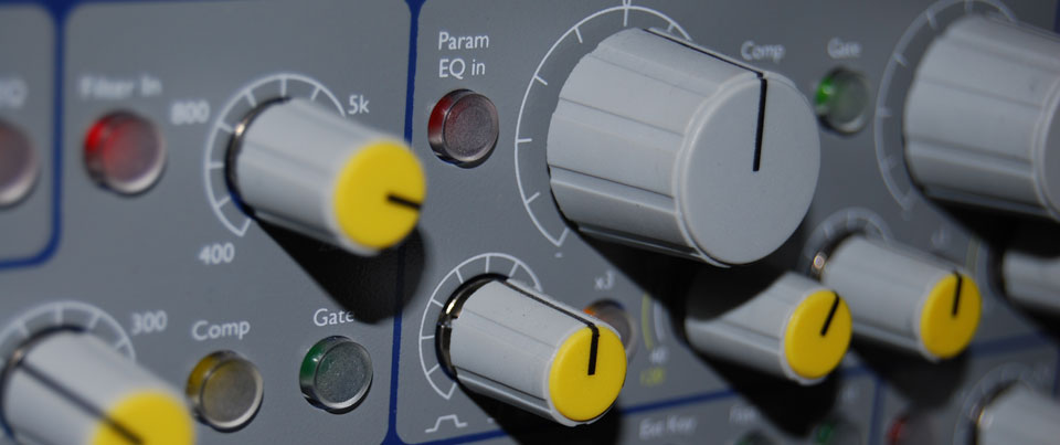
Examples mixer EQ controls.
Equaliser parameters
When we seek to modify a signal by equalising it, we do so by adjusting three parameters; Frequency, Gain, and Bandwidth (Q).
1. Frequency
This control selects the frequency above, below, or around which cut or boost will be applied. With a shelving filter this will be called the cutoff point. With a band-pass or notch filter this will become the centre frequency about which attenuation will take place.
2. Gain
This control will apply boost (increase in level) or cut (decrease in level). With a shelving filter this will cut the sound beyond the cutoff point. With a band-pass or notch filter this will boost or cut the sound around the centre frequency. Boost and cut is measured in decibels (dB). Boost may be expressed by a positive number (eg +6dB) and cut by a negative (eg -6dB). 3dB is the minimum amount of level change needed for the change to be audible.
3. Bandwidth (Q)
With a band-pass or notch filter this control determines how many frequencies around the centre frequency are to be affected, the ‘shape’ or ‘bell’ like pattern of attenuation. It is also expressed as the “Q”.
A low Q (eg 0.3)
will cover a wide range of frequencies.
A high Q (eg 5.0)
will focus in on a more precise and narrow part of the sound.
The Q number is arrived at by dividing Centre Frequency by the Bandwidth (measured 3dB below the peak or above max cut) and is thus a ratio.
Q = CR (centre frequency)divided by BW (bandwidth).
EQ/filter types
There are several types of eq/filter. Each types isolates and boost or cuts frequencies/harmonics in a different manner.
- Low-Pass (shelving) filter
- Hi-Pass (shelving) filter
- Band pass filter
- Notch filter
Shelving filters
A shelving filter applies cut or boost to frequencies above or below a specific point called the filter cutoff point. The equaliser can be said to have cut or rolled-off the unwanted portions of the sound. There are two types ...
1. Low-Pass Shelving Filter
This will let low frequencies pass but boost or cut the high ones. It is often denoted by this symbol ![]()
2. High-Pass Shelving Filter
This will allow high frequencies to pass and boost or cut the low ones. It is often denoted by this symbol ![]()
Filter slope
You can see from these diagrams that rather than stop abruptly the filter slopes away from the cutoff point. This curve ensures an aesthetically pleasing sound. Such an equaliser will typically have a 6dB per octave slope. The slope of the filter is a very important part of an equalisers sound. It is challenging to design and build filters with steep slopes that still sound good. Some of the classic EQ designs employ clever electronics to achieve a good sound.
Poles
The differing slope curves are often referred to as 2-pole, or 3-pole. The following table is a useful reference ...
| db per octave | pole(s) |
|---|---|
| 6dB / octave | 1-pole |
| 12dB / octave | 2-pole |
| 18dB / octave | 3-pole |
| 24dB / octave | 4-pole |
Band-pass filters
This type of filter passes and boosts or cuts frequencies between two limits. On a typical mixing desk the Hi and Lo Mid EQ knobs control band-pass filters. The frequency around which the boosting or cutting appears is called the centre or resonant frequency and is selectable with a sweep control. The degree of boost/cut is called the resonance of the filter and is expressed in dB.
Notch filter
A band pass filter designed to cut frequencies is often called a notch filter.
Equalisers
The filters we have discussed so far are used in a wide range of EQ circuits and devices such as ..
- Portable radio - Basic low pass filter to turn the treble up and down.
- Mobile - simple preset equalizers usually for modifying bass response to compensate for ear-bud style headphones
- Hi-Fi amp - Usually simple 2 band (treble and bass) shelving with fixed corner frequency.
- Mixing desk - wide range depending on cost. The eq implementation has a great deal to do with the sound and therefore reputation of a desk
- Graphic eq - usually used to correct a monitoring systems response within a given room
- Parametric eq - implemented in high end desks, stand alone units and plug-ins
- Synths and sound devices - DAW software, such as Logic and Pro Tools, employ software algorithms to emulate classic hardware designs and create new previously impossible EQ designs.
- Plug-ins
Types of equaliser
Graphic EQ (stand alone hardware)
Recognisable by its rows of faders (on stereo studio graphics generally 30 for each channel) each centred on a particular frequency and spaced one third of an octave apart. Apart from the highest and lowest faders which are shelving, each fader is a fixed frequency band-pass filter. Often used for correcting the acoustics of a particular amplifier/speakers behaviour within a room. The idea is to graphically set up an eq curve by applying cut or boost. Boost is achieved by raising the fader and cut by lowering it. Despite their apparent flexibility it is easy to spoil a sound with a graphic. This is partially because each band is actually wider than a third of an octave and therefore overlaps with adjacent faders producing unpredictable results.
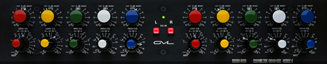
GML8200 mastering eq.
Parametric eq
Essentially the same as sweep band-pass eq but with adjustable filter response width (Q). They may also have adjustable slope controls. They typically have several filter sections allowing different parts of the frequency spectrum to be adjusted simultaneously.
They can be more challenging to set up but are by far the most powerful and are generally considered to be capable of the most pleasing artistic results.
Invented by George Massenberg, in theory all parametric eqs should be capable of identical results. In practice this is not the case due to the different relationships between gain and Q that differing circuit designs have. Some parametric eqs implement a changing relationship between gain and q as gain changes.
Mastering eqs are always parametric and will have a gentle q response for more holistic tonal adjustment. They will often not have continuous controls but feature switch-able knobs which allows settings to be recorded and recalled.
These are implemented in up-market mixing desks but otherwise are to be found in stand-alone outboard form and as plug-ins. The original and in many ways most respected is the original George Massenberg design the GML 8200.
TK Audio's TK-Lizer EQ with a Mid/Side channel isolation mode
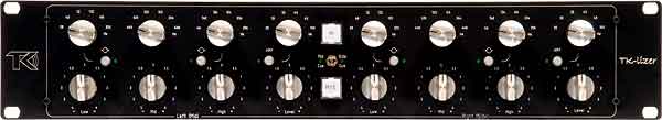
M/S eq
Mid/Side eq involves isolating the middle (mono) information from the side (stereo) information in a stereo mix in order to apply different eqs. You might for example remove low bass in the side signal to create a tighter and punchier bass in the centre.
Sonnox eq plug-in, which includes a GML8200 emulation.
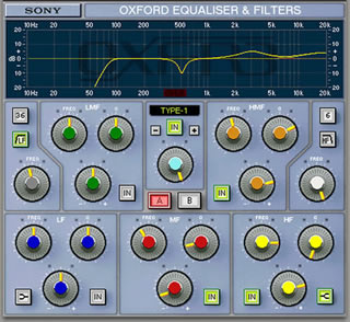
Plug-in software
DAW software, such as Logic and Pro Tools, employ software algorithms to emulate classic hardware designs and create new previously impossible EQ designs.
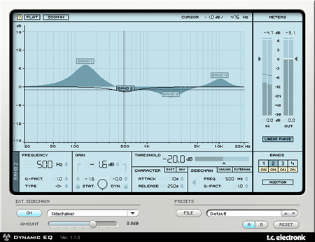
Dynamic eq
This is usually achieved with software and produces a similar effect to frequency conscious compression (side-chain). A frequency range is attenuated only when its volume exceeds a preset threshold level. For example, it may be that one particular note (frequency) in a bass guitar part is too loud. Dynamic eq could be used to automatically turn down the part when that note rises above a preset level.
Mixing desk - typical EQ design
Much better quality today than they once were. Generally split into several bands (High shelving fixed frequency lo-pass filter for treble/Sweep band-pass for upper middle/Sweep band-pass for lower middle/Low shelving fixed frequency high-pass filter for bass). Sound studio mixing desks will have parametric EQ.
TC Electronic PowerCore dynamic EQ plug-in
A typical mixing desk will have four bands of EQ;
1 High Frequency
This will be a low pass shelving filter. Very often there will be a single gain knob offering cut and boost of between -15 and +15 dB. The filter cutoff frequency and slope will be fixed.
2 High Mid Range
Sweep This will be a band-pass filter. There will be a gain control offering cut and boost of between -15 and +15 dB. There will also be a frequency select knob which will allow you to choose or ‘sweep’ between a range of frequencies, typically 500Hz and 16kHz. Bandwidth/Q will be fixed or at best switch-able.
3 Low Mid Range Sweep
This will be a band-pass filter. There will be a gain control offering cut and boost of between -15 and +15 dB. There will also be a frequency select knob which will allow you to choose or ‘sweep’ between a range of frequencies, typically 50HzHz and 1kHz. Bandwidth/Q will be fixed or at best switch-able.
4 Low Frequency
This will be a high pass shelving filter. Very often there will be a single gain knob offering cut and boost of between -15 and +15 dB. The filter cutoff frequency and slope will be fixed.